Structural and geometrical conventions
This page covers Structural and Geometrical conventions for the BHoM framework.
1D-elements
Coordinate system
The following local coordinate system is adopted for 1D-elements e.g. beams, columns etc:
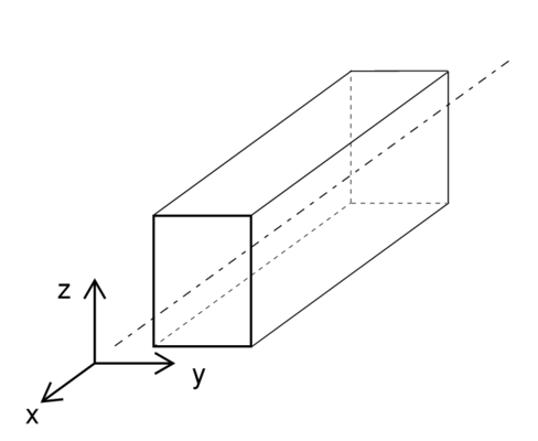
- x-axis along the centre line of the element from start to end
- z-axis as the normal direction of the element
- y-axis transverse to the normal
Linear elements
For non-vertical members the local z is aligned with the global z and rotated with the orientation angle around the local x.
For vertical members the local y is aligned with the global y and rotated with the orientation angle around the local x.
A bar is vertical if its projected length to the horizontal plane is less than 0.0001, i.e. a tolerance of 0.1mm on verticality.
Curved planar elements
For curved elements the local z is aligned with the normal of the plane that the curve fits in and rotated around the curve axis with the orientation angle.
Section property nomenclature
Area - Area of the section property
Iy - Second moment of area, major axis
Iz - Second moment of area, minor axis
Wel,y - Elastic bending capacity, major axis
Wel,z - Elastic bending capacity, minor axis
Wpl,y - Plastic bending capacity, major axis
Wpl,z - Plastic bending capacity, minor axis
Rg,y - Radius of gyration, major axis
Rg,z - Radius of gyration, minor axis
Vz - Distance centre to top fibre
Vp,z - Distance centre to bottom fibre
Vy - Distance centre to rightmost fibre
Vp,y - Distance centre to leftmost fibre
As,z - Shear area, major axis
As,y - Shear area, minor axis
Signs of section forces
The directions for the section forces in a cut of a beam can be seen in the image below:
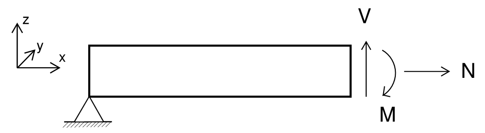
This is: * Normal force positive along the local x-axis * Shear forces positive along the local y and z-axes * Bending moments positive around the local axis by using the right hand rule
This leads to the following:
Axial force Fx
Positive (+) = Tension
Negative (-) = Compression
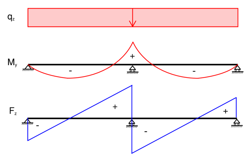
Major axis bending moment My and shear force Fz
As shown in the following diagram.
Minor axis bending moment Mz and shear force Fy
Same sign convention as for major axis.
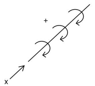
Torsional moment Mx
The torsional moment follows the Right-hand rule convention.
Bar offsets
Bar offsets specify a local vector from the bars node to where the bar is calculated from, with a rigid link between the Node object and the analysis bars end point.
Hence:
- a BHoM bars nodes are where it attaches to other nodes,
- offsets are specified in the local coordinate system and is a translation from the node,
- local x = bar.Tangent();
- local z = bar.Normal();
- node + offset is where the bar node is analytically
- the space between is a rigid link